Monday, December 26, 2011

Shinsei Mountain Man

   No vehicle reinforced my fascination and love for radio control more than the Mountain Man by Shinsei Corporation.  I first saw it in a Toys R Us store in 1984 or early 1985 while browsing (ok, ogling) the radio control vehicle aisle.  It was always the first place I went when I visited any toy store.
Toys R Us used to put their the high-end models on display way high up and above the top of the shelves and out of reach back then.  The display models were usually larger and more powerful than the models on the lower shelves and they had a price to match.  The Mountain Man was one of the most expensive non-hobby grade models available at the time with a price hovering around $120.  I knew of only two stores that sold it:  Toys R Us and KB Toys.   The truck was the same price at both stores.  One time I remember watching an older kid buy a black Mountain Man at KB Toys and I was extremely jealous.  The truck was available in two colors, black and red, but the black one was what I wanted.
   Fast forward to sometime around my birthday in 1985 and my parents surprised me by agreeing to get the Mountain Man for me as a gift.  We drove to Toys R Us one night after dinner and asked if they had any in stock.  After checking inventory in the back, the clerk said only the red one was available.  I relented and agreed to get it.  I don't remember if there was conversion about trying other stores or if it was getting hard to find in stock, but we never tried to find a black one at KB Toys or another Toys R Us location.  It was a small compromise, but one I was willing to make just to have it.
   The truck takes 8 C batteries and 4 AAs for the transmitter.  I bought or already had a set of NiCD batteries for the truck and transmitter, so it was not a big deal to run it.  NiCds were and still are a great way to save money in the long run.  Back then I also knew that NiCD cells would put out more current than alkalines, making the truck more fun to drive.  Later on I bought two more full sets of batteries for the truck after finding an incredible deal on C-sized NiCD batteries at a local surplus store.  The 10 battery NiCD charger from Radio Shack (Archer) was sure a great thing to have, too.  I'd have a set of batteries charging, a set either waiting to be charged or just charged, and a set in the truck.  I could drive almost all day if all three sets were ready to go.
   Within the 30 day warranty period, the electronics in the truck broke.  I had to ship it to the repair facility.  Before I shipped it, I opened it up by removing the body from the chassis in order to see if it was something simple, like a broken or pinched wire.  I found nothing amiss, so away it went to get fixed.  After receiving it back, the repair note that came with it said "cleaned battery contacts" and nothing else.  Now, I knew the battery contacts were not dirty as I had already cleaned them in an attempt to get it working before I shipped it back, so I knew it was not all they did to repair it.  I removed the body and sure enough the whole circuit board assembly was replaced with a new one.  I have no idea why they'd lie about what was repaired, but as long as it worked, I did not really care.  I never experienced another failure.
   I only drove the Mountain Man outside.  I would stay mostly on the driveway, which was paved, but also go down to the stone dust section or the unpaved barn driveway to do some off-roading.  Shifting from 2-wheel drive to 4-wheel drive was done with a sliding switch on the top of the truck (there was no way to shift from the transmitter).  I would spend literally hours driving it around.  The motor driving the back wheels was fairly powerful considering it wasn't a hobby-grade vehicle.  It couldn't do donuts except on slick or dusty surfaces, but it moved pretty good.   4-wheel drive mode was geared down and a second motor drove the front wheels which helped on steep inclines.   The wheels and tires were not really over sized like most monster trucks made today, so it was not a "go anywhere" type of vehicle, but it did a good job.
   I still have the truck and just recently put some batteries in it to make sure it still worked after reading about it on a forum thread I happened to stumble upon.  At first it was acting a little weird, but once I discovered that two of the AA alkaline cells I had put into the transmitter were dead, it started to behave itself.  The battery contacts probably need some cleaning, too.  The truck is most definitely a "runner", and has probably seen a hundred hours or so of run-time in total.  Even so, the tires are still in very good shape with a good amount of tread left on them.   The chassis and body are dirty and have scratches and damage from many rollovers and rocks.  I need to mention that I did try to not roll it over, but sometimes I'd make a mistake on the pavement in high gear 2WD mode.  I never "thrashed" my vehicles on purpose.  Nothing is broken except for a small piece on one wheel rim.  I must have whacked something hard to do it.  The box is long gone, but I still have the manual, however I didn't take any pictures of it.

Not in bad shape, overall, for over 25 years old.


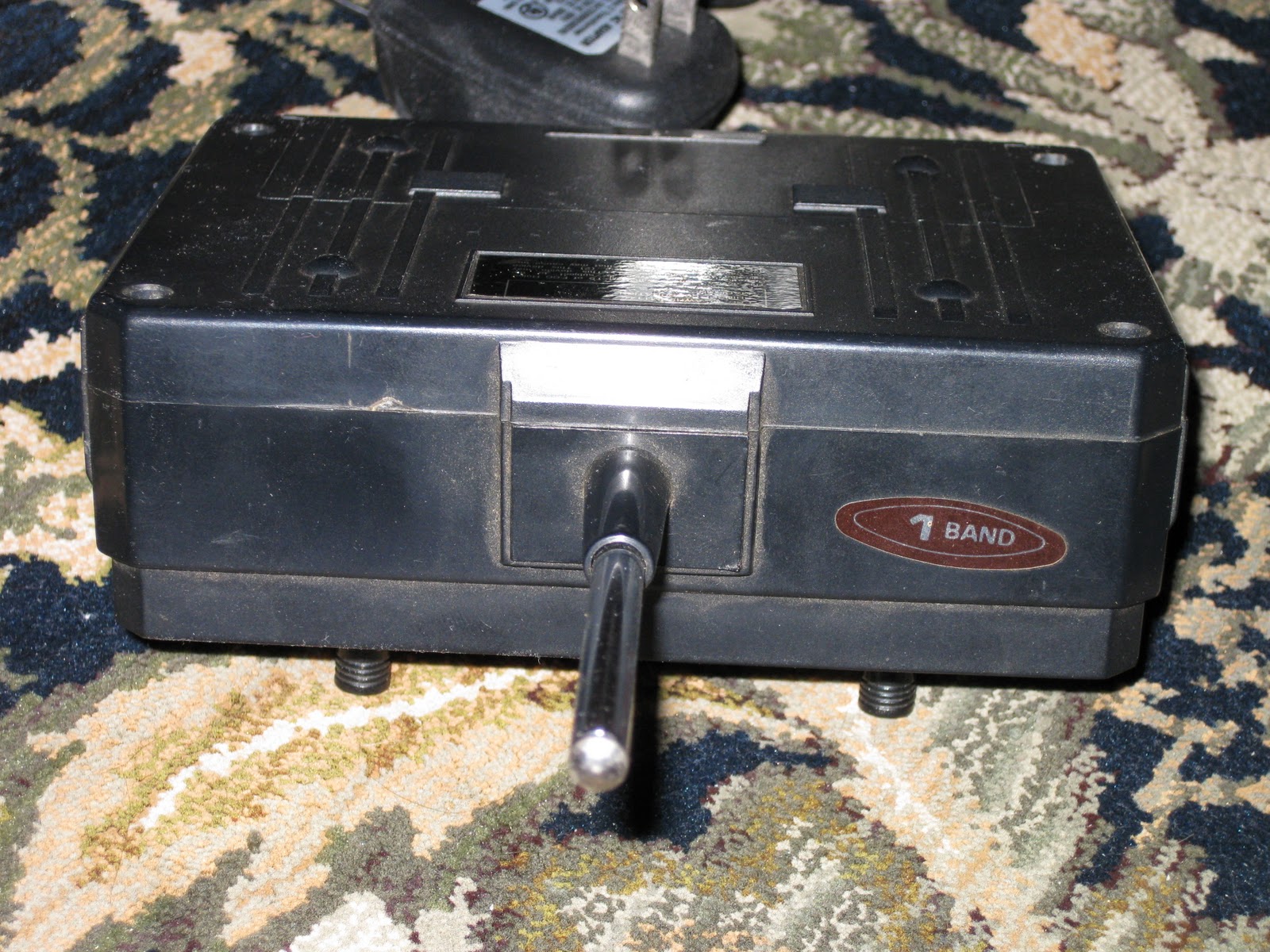
The black version used a different frequency, probably band 2.


The black switch on top flips between high-speed 2WD and low-speed 4WD modes


The spare tire is rubber like the rest.

Many dings and scratches are visible on the underside.  I drove this truck everywhere!

Eight C cells are used in the truck.  The transmitter takes 4 AAs.

Monday, December 19, 2011

Tamiya Buggy Champ and the Gold Edition

   Tamiya released the Buggy Champ in 2009 to much surprise and astonishment in the vintage RC community.  The Buggy Champ was actually the original Japanese name for the Tamiya "Rough Rider" released in the US in 1979.  The reasons for why the names were different in Japan and the US are not clear, although they could be simply because MRC, who was the US importer for Tamiya at the time, thought that the name "Buggy Champ" did not sound aggressive enough for the US market.  I have no facts to back that up, so it is just one possibility.   
   The original Rough Rider was the first of the Special Racing Buggy (SRB) models from Tamiya, which include the Sand Scorcher, Ford F-150 Ranger XLT and (some SRB purists would disagree with me on this) the Super Champ.  The SRB series was an effort by Tamiya to build radio controlled vehicles that were race-ready while still retaining many realistic features from the 1:1 scale vehicles they were based on.
   For the 2009 re-release, Tamiya kept the Buggy Champ name for the US market.  The reasons behind this choice are not clear either, but may have to do with trademarks on the Rough Rider moniker or because TamiyaUSA, now the sole importer of Tamiya products for the US, did not care how non-aggressive the Buggy Champ name was and decided that it was cheaper to use the same box art in all countries.  Again, I have no facts to back any of this up, so it is just an idea.  
   While not exactly the same as the original 58016 Rough Rider kit, the 58441 Buggy Champ is considered a "re-release" because it contains mostly the same parts and design elements that made the Rough Rider and the SRB platform such a vintage classic.  Tamiya even recreated the blister packaging that was so popular in the early eighties, which is really impressive to look at in person.  Many enthusiasts, me included, believed that Tamiya would never release such a kit again due to the sheer amount of metal parts and expense in manufacturing that goes with it.  As it turns out, Tamiya did not even have the original molds used for the major metal components for the chassis and had to create new ones based on an original example vehicle that Tamiya had in its possession.  The Tamiya engineer in charge of this effort claimed that it took only a couple of weeks of work to get the measurements required to make new molds.  I think that is impressive, and shows how much effort Tamiya is willing to expend in order to re-release kits.
   The Buggy Champ Gold Edition was a special edition of the Buggy Champ created by Great Planes Distributing and TamiyaUSA.  Great Planes is one of the largest radio control distributors in the US and is the place where almost all hobby shops and online stores get their Tamiya kits and parts.  Their marketing department wanted to create an exclusive edition of the Buggy Champ, so the Gold Edition was born.  The following pictures were taken by me shortly after receiving the Gold Edition of the Buggy Champ from Tower Hobbies.  I was one of the first to receive and post pictures of it on TamiyaClub using my Photobucket account.  Members of TamiyaClub were anxious to see what it was all about.  As it turned out, the only differences between the regular Buggy Champ and the Gold Edition were the painted body and stickers on the box.  The body was painted in Tamiya TS-84 Metallic Gold, but the roof section was not painted, probably because it was still attached to the parts tree and would have been difficult to paint quickly without getting paint on other parts that did not need to be gold in color.  Pricing on the Gold Edition was actually cheaper than the regular version, which was one of the reasons why I bought mine.  The gold can be sprayed over or left as is, so it does not detract from the regular kit at all in the grand scheme of things.
  

Special Gold Edition sticker distinguishes from the regular box

The blister packaging on the left and right sides display the major parts in a neat way


Same body as the regular kit, just painted in TS-83 metallic gold

The Tamiya TEU-104BK ESC was included

Since there was no official kit number for the gold edition, 58441 had to be covered by a sticker
The Buggy Champ Gold Edition is now discontinued by Tower Hobbies, and Tower no longer sells the regular edition either, however TamiyaUSA still has the regular kit in stock (at a premium distributor price so as to not compete with local hobby shops), so you could still have good luck finding a Buggy Champ at a local hobby shop.

Monday, December 5, 2011

White Lettering on Tires

I've never been a fan of painting the bodies on my cars, so painting the tires never even crossed my mind, at least until I saw fellow modelers do it on their cars.  It is practically expected nowadays.  For example, after I built and painted a re-re Tamiya Sand Scorcher and posted pictures of it on TamiyaClub in 2010, a couple members replied that I needed to paint the letters on the tires to make it look complete.  I agreed with them, but at the time I did not have a method for doing so that did not seem completely tedious or error-prone.  Threads have popped up every so often where someone asks how to paint the letters on tires.  The responses are usually limited to using white paint and a toothpick, or a pin or similar and just letting it flow into or onto each letter on the tire.  I always considered that method extremely tedious and time consuming.  It is a time honored method, but not one that I felt that I had the patience or skills for.  I guess I am not a true "modeler" in that sense.  I always imagined a drop of white paint splotched in between two letters because I put too much on the end of the toothpick and it dripped before it got to its final destination.  Or the paint would dry on the toothpick too quickly and wouldn't flow into the letters.  With these thoughts in my mind, I gave up before even trying anything.

But, a recent post on TamiyaClub (http://tamiyaclub.com) that described a white ink pen that can be used instead of toothpicks got me excited enough to give it a try.  The pen is made by Sakura, a company headquartered in Japan, and it's called the Gelly Roll(R) ink pen.  Their US website Gelly Roll(R) product page (http://www.sakuraofamerica.com/gelpen) doesn't even list white as an available color, but it does exist.  I located a supplier on the net and had a pack of three pens in my hands a few days later.
Three-pack of Sakura Gelly Roll pens with white ink

The pen is actually a ball point, which I'd never thought could be used for painting tires.  The ball is 0.8mm in size which is considered medium point and draws a 0.4mm line.  I did not see any fine point 0.6mm ball (0.3mm line) pens with white ink when I looked, but they may be available for finer lettering.
Close-up shot to show the 0.8mm ball point
Armed with this new tool, I decided to try painting the Sand Scorcher tires.


It took me around 10 minutes per tire.  It isn't easy keeping a steady hand for 30 characters per tire.  The way I did it was to basically draw each letter, allowing the ink to flow in between the outline ridges that make up each character.  I was really happy with the result at first, but then I noticed that the letters were not completely filled in after they dried.
The zero and second one digit are not filled in completely
I had not allowed enough ink to flow into each letter, thus capillary action and surface tension made the ink stay in the corners of the letters and away from the flat bottom, much like water sticks to the inside corners of plastic containers when you wash them.  I could go over the letters again, but since it is only noticable up close, I'm not going to attempt to fix these tires.  I'll simply modify my method for the next set.

Next up was the Tamiya Subaru Brat and its Sand Blaster 915s. 

Now these letters are much larger and wider than the ones on the Sand Scorcher.  I made sure to allow each letter to be filled with a pool of ink by lifting the ball of the pen away from the surface of the tire slightly while following the contours of the symbol.  This caused the ink in the pen to flow past the ball point and fill in the letter.  Now this was impressive!  The ink is nice and opaque and flows very well.  The ink dries within about 10 minutes.

Lastly, I did another set of Smoothee and Padlatrak tires from my Tamiya Grasshopper.


This time I made sure to allow each letter to fill in with ink, and the result is that there are no dark areas in the middle of each letter.  So the key is to allow enough ink into the letter to create a pool.

As for how durable the ink is, I have not tested it to find out.  A toothpick or fingernail will remove the ink on the raised edges of the letters, so I predict that the ink will come off if it is scratched or rubbed inside the letters themselves.  On paper, the ink is very resistant to chemicals and is quite difficult to remove.  Rubber, however, is a tough thing to write on.  But I am not looking for durability here.  My cars are runners, and I don't mind the normal scrapes and bruises that happen during normal running.  If the ink comes off, I can always touch it up again.


I'm very pleased with the results so far.  If you've been afraid to paint the letters in your tires, give the Sakura Gelly Roll(R) pen a try.

Monday, November 28, 2011

The Futaba 3UCP: My Radio System of Choice

I am old school when it comes to radio control systems.  All of the store-bought cars and trucks I had as a kid were controlled by 2-stick transmitters, so when it came time to purchase the radio system to go with my brand new Tamiya Super Champ kit in 1984, I chose a 2-stick system from Futaba.   Back then pistol grip transmitters were unheard of, if in fact they existed at that time (I honestly cannot remember).  

The radio system I got to control the Super Champ was the FP-T2NL Attack with FP-R2GS 2 channel AM receiver and two S28 servos on channel 82 (75.830MHz) in the 75MHz band.  It was a low-end radio system, being AM and only 2 channels, but back then 2.4GHz did not exist, and FM was relegated to the elite few that could afford the higher price of less glitchy control.  I certainly was not one of them.  Having been used to the cheap AM transmitters included in the store-bought cars, the Futaba Attack system was an incredible upgrade in terms of workmanship and feel.  The transmitter felt heavy, especially with the 8 AA batteries installed.  The plastics looked and felt high quality.  The sticks were knurled and machined aluminum.  The gimbals were incredibly smooth and precise.  There was no side-to-side wobble and no stiffness or weird resistance to movement like the cheap toy transmitters I was so used to.  Just precise control.  The sticks felt like they were supported by ball bearings to my inexperienced hands, even though they weren't.  The servos directed the horns exactly where the sticks told them to, every time.  There was even a voltage meter on the front, which, when the radio was turned on, showed the output level of the batteries so you'd know if it was time to replace them.  I had finally made the leap to "hobby grade" radio control, and it was awesome.  I still have that radio system, and it still works fine.  It's old and dirty and it's not mounted in any of my cars any more.  Only one thing could make me retire that system:  A better radio system.

In the early 90's, pistol grip systems were becoming more popular.  The major brands like Airtronics and Futaba were designing some very sophisticated radio systems for cars and boats.  But I was still used to the 2-stick transmitter.  It was what I grew up with.  I mean, I could get used to a pistol grip, but I still had a preference for thumb control.  There were a few reasons to want to upgrade the radio system I was using for my growing fleet of ground and water vehicles.  First, AM was beginning to take a back seat to FM, and then PCM, and the greater precision and resistance to interference was getting more important in my eyes.  Watching one of my vehicles go off on its own into a curb or other immovable object was not something I wanted to see more than once.  Believe me, I had seen it, and it was not pretty.  These cars were not cheap and back then I wanted to drive, not fix broken A-arms.  Second, the trim settings for each vehicle were slightly different, and it was a pain to reset them each time I switched to another vehicle, so multiple model memory was required.  Third, the FCC had just changed the rules for the radio control spectrum, and narrow band was now mandatory for all new radio systems.  The old radios were still allowed for a few more years, but the writing was on the wall for my old system.

Then, I saw the radio system of my dreams:  The Futaba 3UCP Field Force 3.  The 3UCP was a 2-stick, 3 channel radio system that used Futaba's PCM1024 technology, which, at the time, was some of the best technology available.  It came with the R113iP PCM1024 3-channel receiver and two S9301 servos.  It had everything I had ever wanted in a radio system, but the price was way out of my league.  I was still in college at the time, with no job, so there was no way to afford a luxury item like that.  At least not until I graduated and started making money. 

After graduating in 1993 and getting a job later on in the year (there was a small recession back then, remember?), I finally had some money that could be spent on "toys" such as these.  Futaba was still making the 3UCP, so I bought one.  Finally, I got what was the absolute top of the line 2-stick radio system ever made by Futaba for ground-based vehicles at the time.  It was computer controlled, with a large LCD screen, 6 model memory, programmable mixing, throttle exponential, dual rates, sub-trim, 4-wheel steering, tilt, twin servo control, lap timers and more. 
The Futaba 3UCP Field Force 3 PCM1024 transmitter

It was so complicated that it scared me a little.  I had to learn what all of these functions did, and get used to the terminology.   There was ATV, D/R, EXP, and CURV to name a few.
Just some of the display/setup screens on the 3UCP

My only wish about the 3UCP:  A way to program the name of the vehicle, even just 3 or 4 letters, in each memory slot.   As it is, I have to keep a piece of paper with each transmitter to know which model number goes with which vehicle.  It's really the only complaint I have about it.

The 3UCP was never very popular in the United States, mostly because it was a 2-stick design.  Most big-name and club racers were using pistol grip transmitters.  Also, it was very expensive at around $380 in 1994.  This price was significantly more than its pistol grip counterpart at the time, the 3PB Magnum PCM1024, which sold for approximately $290.  Futaba stopped production of the 3UCP sometime in 1996.


Fast forward to today, and I'm still using the 3UCP to control all of my ground-based vehicles.  My fleet of vehicles has grown over the years to around 24 running models and many more still in kit boxes, waiting to be built.  I now own five 3UCP transmitters and 30 R113iP receivers, exactly enough to max out each transmitter's model memory.  Four out of the five sets I have were brand new when I got them, and the 5th was in very good condition and only needed a new FP-TP-FM transmitter module to make it complete.  As it turns out, the TP series of modules are hard to find in 75MHz ground format, but I finally got one.
My "fleet" of 3UCP radios.

I keep all of my 3UCP transmitters in radio cases for protection from dust and damage. 

I have upgraded the batteries in each transmitter using an 8 cell 9.6V NiMH 2200mAh pack from http://www.batteryspace.com.  The battery pack fits in the compartment along with some foam and uses a connector for easy replacement.  I had to open each transmitter in order to solder the connector, but it was very easy to do.  Now there are no more corroded 9V connector tabs and wimpy Futaba 500mAh NiCd battery packs.  The runtime is something like 4 hours.


My next plan was to buy one of Futaba's newest flagship 2-stick radio systems, the 2.4GHz 3VCS, however Futaba recently discontinued it and removed it from all storefronts.  I really wish I had bought one when I had the chance since it is impossible to find now.  The 3VCS seemed like a worthy successor to the 3UCP.  Now I don't know what I will do once I max out the model memory on these.

Wednesday, November 23, 2011

Kyosho Lazer ZX restoration

This summer I rebuilt my Kyosho Lazer ZX chassis that I've owned since around 1993 when I bought it from a high level manager's son at the company where I worked.  The body was tattered and painted poorly and the front gearbox was punctured with a hole in the front of it.  Also the spur gear was ruined because the pinion mesh with the spur must have slipped too far apart causing the teeth to get shaved down.  In those days parts were still fairly easy to come by, so I ordered a new front gearbox set (LA-32) and spur gear (LA-2) from Tower Hobbies (http://www.towerhobbies.com).  Back then Tower used to carry Kyosho kits, parts, and hop-ups.

Speaking of hop-ups, when Tower was beginning to clear inventory of Kyosho-related parts in the 90's, I bought some Lazer parts made by Kyosho, A&L and also some Tecnacraft titanium tie rods for good prices.  I had actually ordered more parts than they had in stock, so unfortunately I missed out on some really cool pieces because other people had already purchased them before me.  After installing the parts, I didn't really run the car very much because I was not into 4WD back then.  Plus, the design of the center diff and front and rear one-way pulleys confused and irritated me because the rear wheels seemed to never get any forward power.  I even locked the center diff to get more power to the rear wheels.  The car sat in the basement for 18 years, untouched. 

Then this year I got sick of looking at the sad state the chassis was in, so I made it my mission to rebuild it completely.  I disassembled every screw and nut and cleaned everything as best as I could to make all of the parts look as new as possible.  I also purchased some new LA-43 ball ends, OT-32 balls, #1285 2.6mm hole black steel balls, diff balls, diff plates and all new ball bearings to replace the original parts because they were either too worn or binding up.  Then I laid most of the parts out on my workbench and took a picture:

The hop-ups laying on the table include:
  • A&L Front suspension mounts (I missed out on the rears)
  • A&L #3806 Finned motor plate
  • A&L #3807 Steering bell cranks with bearing
  • A&L #3808 Front deck support
  • A&L #3809 Rear deck support
  • Kyosho LAW-01 FRP front and rear shock towers
  • Tecnacraft #1019 Titanium Lazer tie rods
Close up shot of the vintage hop-up parts

I purchased a reproduction Lazer ZX body, wing, and decal set from Marwan (http://marwanrc.com), however I never got around to painting this year, so it still sits in a box waiting for next summer.

I also bought modern Kyosho wheels and tires designed for the Lazer ZX-5, along with a set of new hex hubs. Finally, I bought some shock rebuild kits, new rubber diaphragms and shock shafts for the Kyosho Gold shocks.  The part numbers for these are as follows (available at http://kyoshoamerica.com): 

  • W5018  O-Ring set (Gold shock) (2 sets are required for all 4 shocks)
  • W5181-08 Shock shaft (S)  (for the front shocks)
  • W5182-02 Shock shaft (M)  (for the rear shocks)
  • W5189-05 Diaphragm (Black/4Pcs)

The original belts were slightly worn in some spots where some small pieces of debris got caught in the teeth, but I decided to use them anyway since they seemed to still be in good enough shape.  I have a set of Tough Racing brand belts, though I've heard they are not as good as the originals, especially when using a powerful brushless motor.

Once I got all of the parts I needed, I followed the instruction manual and rebuilt the chassis using the original, vintage hop-up parts and the new parts.  Here is the result:


The rebuilt Kyosho gold shocks are smooth as silk, just like new.  The modern wheels and tires fit perfectly and look nice with plenty of clearance around the arms, hubs, carriers and upper camber links.

The motor is a Kyosho Mega 16x2 4WD with ball bearings.  I originally had this motor installed in my Turbo Ultima, but since I used the stock Kyosho 240ST in that car for its restoration last year, I decided to use the Mega 16x2. The ESC is a Novak 410-M5.

I used the 18 tooth hardened steel pinion that came with the car when I bought it to perform some maiden test runs sans body.  I have a Kyosho W5086 48P 16T hard pinion in case the car feels over-geared.  The car really flies and is very quiet due to the belt drive.  After a couple of driving sessions, the spur gear differential needed some tightening because the rear wheels were still not transmitting as much power as they should.  The motor and ESC were not hot after a good run, so I think I'll leave the 18T pinion on for now.

It was a lot of fun to restore this car back to running status, and the vintage hop-ups give it some uniqueness.  Once I paint the body next summer, I'll post some pictures here.

Saturday, November 19, 2011

Turbo Ultima steering bellcrank upgrade

After installing the Ultima RB5 front axles and carriers and replacing the tie rod ball ends, there was still a lot of steering play from the hubs all the way to the steering servo, a Futaba S132H.  The original Turbo Ultima steering design was rather sloppy to begin with due to the use of bent wire and oversize holes in the steering bell crank assembly.   Even when new I was not happy with the design of the bent steering rod that went from the servo horn to the bell crank, but it worked so I left it alone, even for the restoration in 2010.  Well, no more.  I wanted that steering slop eliminated as much as possible.

Earlier this year I was searching for vintage parts on the net and discovered that A&L parts were being produced again from the original designs.  If you were into RC back in the late 80's and early 90's you'll recognize the A&L name.  Well, Daryl Lane (the 'L' in A&L) is operating Factory Works (http://www.factoryworks.com) and also selling reproduction A&L parts at http://vintageteamaandl.com.

One of the parts A&L has re-released is the steering bell crank assembly for various vehicles including the Associated RC10, Kyosho Ultima, Kyosho Optima Mid, and more.  According to the web site, the original plastic molds are the same, but the color of the plastic is now a darker yellow in order to differentiate from the original parts.  I never owned the original parts, so I cannot say if this is true or not.  The new parts are, at least to me, fairly bright yellow, so the originals must have been day-glow or something if they were even brighter.

I ordered part #2180 from A&L which is the Ultima bell crank assembly with ball bearings since I did not have any bearings of the correct size in my stock.  I also ordered a Tamiya servo saver assembly from another online hobby shop because my Turbo Ultima never had one installed.  Why Tamiya?  Well, I didn't know of any part numbers for Kyosho servo savers and I knew the general design of the Tamiya was exactly what I wanted.

Here are the parts cards for the servo saver and ball ends:


Unfortunately I did not take a picture of the A&L steering bell crank kit in its packaging before I opened it and started assembly, but it was a simple plastic heat-sealed bag with no header card separated into three different compartments.

Installing the steering bell crank kit took a fair amount of time because I had four inter-related and connected things to consider:
  1. Which bell crank parts to use (it comes with a left and right so you can decide the best orientation for your particular vehicle).
  2. How to position the steering servo.
  3. Which parts of the servo saver I was going to use (it comes with a short and long servo horn).
  4. I had to design a new steering tie rod that goes between the servo saver horn and the new bell crank assembly.  I wanted to use a Tecnacraft rod if possible.

I ultimately positioned the servo in the chassis so that the back of the servo was hitting the side wall of the aluminum frame, and flipped the servo mounts backwards so the holes at the bottom of the frame lined up with the servo mount holes and the servo mounting tabs.  The servo output shaft is positioned toward the front of the vehicle in order to allow the use of the large servo saver horn supplied with the Tamiya servo saver kit (part Q 2).  The large horn protrudes above the upper deck of the chassis, but the upper deck FRP plate has a factory cutout that allows complete freedom of movement for the horn.  It works so well it's like it was designed that way.

I should mention that the only reason this mounting design works is because of the Futaba S132H's short body.  A regular sized servo would not work as nicely.  The angle of the steering rod to the bell crank would be even worse from the ideal 90 degrees than this.  Secondly, I had to reduce the steering dual rates on the transmitter to somewhere around 67% in order to limit servo travel in both directions and prevent binding at the steering extremes where the cranks hit the frame.  It can't steer any more than that, so maximum steering is achieved.  I do not know if it is possible to use the shorter servo saver horn because the extra travel required by the horn and the fact that the steering tie rod is connected to the inside may cause binding when the servo pulls back because the tie rod ball end would hit the servo saver body itself.

 
I used one 10mm and one 15mm Kyosho ball end with a Tecnacraft tie rod to form the steering tie rod linkage.  It just worked out that way due to the limited selection of tie rod lengths I had to choose from.  The ball stud and nut came with the Tamiya servo saver assembly kit. The same style ball stud was used on the other end mounted to the bell crank but no nut was needed.  I drilled the mounting hole a little wider in the bell crank before screwing in the ball stud because it seemed like it was designed for a 2.6mm screw, while the stud was 3mm and I didn't want the bell crank to split.

Two yellow combination mounting nut and bearing posts hold the steering assembly to the main chassis frame using long flat head screws pushed up from the bottom frame.  The bell cranks, with bearings installed, fit over the mounting posts.  White plastic nuts are used to hold the bell cranks in place so they don't "lift" up and off the posts during use.

The black fiberglass steering plate comes with the A&L steering bellcrank kit.  Two screws and shims connect the steering plate to the bell cranks.  No bearings or bushings are used for these pivot points, which is a little disappointing.  I hope the screw threads don't chew through the steering plate over time.

Perhaps some structural rigidity is lost because the A&L bell crank mounting screws do not reach the top chassis plate.  I think with some work the screws and bearing posts could be replaced with aluminum posts of the appropriate width and length.  A stepped design to the post could be used to keep the bell cranks at the bottom where they belong.  Then the original kit machine screws that held the original bell crank posts could hold the new posts in place, keeping the structural rigidity the same as the original design.  If I had the resources, I'd try it, so for now it is just a dream.

I had to switch to shorter Tecnacraft steering tie rods again due to the change in geometry created by the new steering assembly.

So, after all of that, did it work?  In a word, yes.  The steering slop is completely gone.  In fact there is now more play in the outer hinge pin/steering hub than in the whole steering system.  The A&L steering bell crank kit is very highly recommended.

Turbo Ultima front end and wheel/tire modernization

I restored my vintage Kyosho Turbo Ultima during the summer of 2010.  For the restoration, I completely disassembled and cleaned every part, and then followed the manual to rebuild it.  I also bought a reproduction body, wing and decals from Marwan (see his new online store at http://www.marwanrc.com).  The body and wing were painted and decals applied in the original box art design.   I also kept the vintage aftermarket Tecnacraft tie rods because they still look really nice and a lot better than the original steel tie rods.

Here are a couple pictures taken after the restoration was completed in July 2010:

 
The tie rods were the only hop-up installed on the car at the time.  

Last week I installed a Kyosho Ultima RB5 front end and fitted RB5 wheels and Kyosho tires.  The point of this was to use modern wheels and tires in order to run the car without using up the original tire tread.  Plus, it seemed like a fun thing to do and maybe a little challenging.  It was actually very easy to do, which I found amazing considering the almost 20 year difference in chassis design.

For help in determining the correct parts to buy and also to aid in building the front axle assembly, I referred to a Kyosho Ultima RB5 manual in PDF format that I found on the net.

Here are the parts I used for the front end:

 These parts were used for the wheels and tires:

New tie rod ends and balls were used because the originals were too worn or were binding.  I should have replaced them when I rebuilt the car in 2010, but I didn't have the parts and at the time I was concentrating on keeping as many of the original parts in the rebuild as possible.  Now, however, since the front end is getting modern parts, I figured the ball ends should be redone at the same time.  At least Kyosho still makes some of the exact same parts as they did in 1989.

Here are some pictures of the RB5 front end parts mounted on the Turbo Ultima.


Some adjustment had to be made to the lengths of the tie rods for both the steering and upper links.  I had to find alternative lengths of Tecnacraft tie rods, too.  Luckily I had some in the correct lengths.  I kept the original front arms and hinge pins.  An aluminum spacer was used on the hinge pin that holds the hub carrier to take up extra space, but it's almost the same as the way the RB5 builds it.

Amazingly, the modern Kyosho rear wheels give plenty of clearance when using the original Turbo Ultima rear axle carriers, W5061 universals, hex hubs, and tie rods.

Here is a shot with everything fitted:

The new wheels and tires definitely give the car a more modern appearance, but I think it looks good.  And now I can run it without worrying about the original wheels and tires.