Showing posts with label build. Show all posts

Monday, August 24, 2015

Kyosho Lazer ZX Restoration Finished

I have finally finished the Kyosho Lazer ZX restoration that I have been meaning to get done for what seems like forever.  The last time I posted about this car was way back in late 2011 when I completely rebuilt the chassis from scratch.  The rebuild included some vintage hop-ups and original repair parts that I had bought not too long after I acquired the car way back in 1993.  If you haven't read that post before, I recommend viewing it before continuing with this one.  Here are a couple pictures from the rebuild:


The final piece of the restoration that was missing was the body, under tray and wing.  I had bought a reproduction body and decal set from MarwanRC in 2011 with plans to finish the work during the following summer of 2012, but that never happened.  Other things came up, plus I didn't feel like I was in the right mood to do it justice.  I knew it would be a difficult body to fit to the chassis.  I also knew masking the body for the box art color scheme would be a fairly complex undertaking.  I figured the painting itself wouldn't be too difficult to do as long as the masking was done properly.  It's just two colors, after all.  One sticking point was the yellow trim lines between the two main blue and white colors on the body. How would I do that?  Triple mask for three colors or trim tape on the outside (or even inside) the body?  My own self-doubt prevented me from attempting the work.

Fast forward to now, in the middle of summer 2015 in the northern hemisphere, and I can say that I have finally finished one of the most complex body fitments I've ever done.


Here is a quick overview of the work involved.

There were four main steps to finishing the Lazer ZX body set:
  1. Cutting, trimming and testing fitment of parts to the chassis
  2. Masking
  3. Painting
  4. Decaling
Cutting, Trimming and Fitment
Trimming the body parts and getting them to fit the chassis took the most time for this body set.  There are four parts to the Lazer ZX body set:  The main body shell, under tray, main wing and secondary wing.  This is twice as many parts as a "normal" car, which usually has just the main body and wing.

Fitting the main body shell to the chassis took the most time due to the complex cutouts required around the front shock tower, rear shock tower and right side gearbox.  Lots of fine-tuning the fit was required so that the body did not press or rub against the chassis, gearbox cover, and shock towers.

The main wing was the second hardest part to cut out and trim.  As wings go, it's pretty normal in shape but I find that it takes me a while to trim it down to the proper shape while keeping the edges straight and even.

The under tray was fairly simple to cut out and trim due to its mostly flat shape and straight edges.  Some extra trimming was required in a couple areas to allow the tray to fit more closely to the underside of the main chassis and prevent it from being stressed at contact points.

The secondary wing piece was the simplest part to trim and fit.  It's just a wide U shape with a center notch cut out to fit around the main wing mount bracket.  It fits inside the main wing in the finished product to create a "double wing" design.


Masking
Masking the body parts took the second longest amount of time to complete.

For the main body, the main cockpit window was masked first.  I know the box art scheme has a black window, but I wanted it clear instead.  Then, the areas I wanted white were masked off.  Remember, dark colors, like the metallic blue I used, are sprayed first when painting polycarbonate bodies from the inside.  After masking was complete, the areas I wanted painted blue were the only sections exposed.

The main wing needed a white stripe down the middle, so I masked it off, making sure it was evenly spaced on both sides.

The under tray and secondary wing pieces needed no masking because they are all blue and all white, respectively.

Painting
I used Tamiya PS-16 Metal Blue and Tamiya PS-1 White straight from the can.

This step is probably the simplest, but at the same time one of the most frustrating.  The very narrow space on each side of the main wing makes it practically impossible to get spray paint there.  I kept spraying and spraying, but the paint wouldn't go in.  In the past I've moved the paint can nozzle closer to the wing but it usually results in too much paint hitting the surface which ruins the metallic effect or results in a dreaded run.  I'd rather have it be too light in color than possibly have a drip or run.

The rest of the body parts painted nicely.  The main body was easy to do.  Many light coats were applied until it became mostly opaque.  I wanted a dark, rich metallic blue color and I knew white would be backing it so I made sure the paint was thick enough not to have the white affect it too much.  The under tray was the easiest because it was mostly flat which allowed the paint to coat it evenly.  

After the blue paint was applied and left to dry for a while, I peeled off the masking which exposed the parts of the body I wanted to be white.  The cockpit window mask was left in place.  I sprayed the entire main body, main wing and secondary wing with Tamiya PS-1 white until it had nice coverage.  After the white was dry, I removed the cockpit window mask and then removed all of the protective film covering each part.  I let it dry for a few days before moving on to applying the decals.


Decaling
I think that applying decals to a body is the most enjoyable part of the work.  No fiddling with sharp knives under tension, no plastic shards and no dust.  Also, there are no smelly paint fumes to deal with.  Just plop down in a chair with the TV on and play a bad movie while carefully cutting decals, dipping them in a soapy water solution and sticking them to the body.

It is certainly a time consuming process, but very straightforward.  Each decal has a specific location where it needs to go and it is just a matter of cutting it out from the sheet and positioning it precisely on the body.  The soapy water really helps with the final positioning.  It lets you move the decal around instead of just having it stick where the decal happened to touch the surface of the body.  It's also possible to remove the decal, re-dip in the soapy water solution and place it down again to get more time for positioning.  The larger decals benefit from this more than the smaller ones, but when trying to get the perfect spacing every trick has to be used.

With the main decals finished, there was just one more thing:  That yellow trim line between the main blue and white colors on the main body.  I purchased some Pactra Trim Tape in yellow which comes as a roll of 8 different widths ranging from 1/32" to 1/2".  I used the 1/16" wide strip. 

[Side note:  I discovered during my research for trim tape that Testors, the company that owns the Pactra brand, had begun to phase out most Pactra products as of mid-2013, including trim tape.  You can still find it, however.  It is also available under the Testors name, although the rolls are not as long.  It comes in various colors, including blue, red, yellow, silver, white and black.]

I did not use any soapy water with the trim tape.  It was strong enough to withstand removing and re-applying it over and over to get it in the correct position, so I decided that the soapy water wasn't necessary.  It bends around curves and corners well.  It is important to not stretch it as it is being applied, especially on concave surfaces.  After a few hours it will try to return to its original length, so it will pull back and away from the surface.  Use of a hair dryer or heat gun helps activate the adhesive and relaxes the tape, allowing it to adhere to the surface better.


Final Result
It is perfect?  No, certainly not.  I made a couple of rookie mistakes, like not ensuring that the masking tape was firmly pressed down in a couple places which allowed some paint to go under the tape where it shouldn't have.  I always seem to have a couple spots like this.  Luckily the two spots on this body are not too noticeable.

Am I happy with it?  Yes, for two reasons: First, it's finally done after all these years.  It is certainly a good feeling of accomplishment.  Second, it looks quite nice, especially in person.  These pictures don't really do it justice.  I am my own worst critic because I know every flaw, every mistake and every shortcoming about it.  I wish I could have done a better job than I did.  But it is what it is.

Enjoy these pictures of the final product.

Vehicle: Kyosho Lazer ZX (originally released in 1989)
Body: MarwanRC Reproduction Lazer ZX
Decals:  MarwanRC Reproduction Lazer ZX
Trim Lines: Parma Trim Tape (Yellow, 1/16" width)
Paint Scheme/Layout:  Lazer ZX Box Art

This first set of pictures show the vehicle with the following wheels and tires:
  • Wheels:  J.C. Racing 2.2" Yokomo YZ10 5-Spoke
  • Tires: Pro-Line Racing Caliber 2.2" (8211-02 front, 8210-02 rear)


This second set of pictures show the vehicle with the following wheels and tires:
  • Wheels:  Pargu2000 Aluminum Optima Mid Front Narrow Wheels (ms0020)
  • Tires: MarwanRC Reproduction OT66 (rear), Kyosho Square Pin Narrow (front)


Monday, August 5, 2013

Kyosho Raider Restoration (part 3)

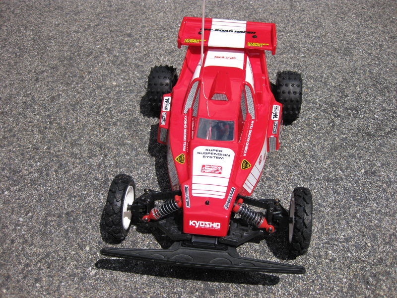
On to the final part of this Kyosho Raider restoration: finishing the body, wing and wheels.

In the past I have generally used curved lexan scissors to trim polycarbonate bodies.

Duratrax lexan scissors

These scissors are specially designed to aid in trimming excess lexan due to the curved shape of the blades.  They work quite well for general trimming and going around outside corners, but I've found them hard to use around tight inside corners, especially if the lexan is thick and won't bend out of the way easily.

Another method modelers use to trim lexan is a technique called scoring.  Using a sharp knife, a score line is made along the body either right on or just outside the molded trim line.  The depth of the cut does not have to be very deep to be effective although deeper cuts do help in cases where the lexan is fairly thick.  Once the body has been scored, strategic cuts can be made using lexan scissors or the knife blade to allow the excess lexan to be bent and or ripped along the score line.  The resulting edge is quite clean, similar to how glass is scored and broken to create a clean edge.

I used the scoring technique on this Kyosho Raider reproduction body and wing from Team Bluegroove due to the many curves and thickness of the lexan.  Using a brand new X-Acto #11 blade, I scored a trace line on the outside of the body, cutting through the protective blue plastic layer and into the body.  The key is to make a continuous score line so the plastic can be bent and ripped apart cleanly.  When separating the trimmings from the body it helps to go slowly in case the lexan doesn't want to follow the score line as it is ripped apart.  A body can be ruined very quickly if the lexan rips into the wrong location.  The knife can be used to help cut in places where it looks like the score isn't deep enough.

Once the excess parts were trimmed and the body was separated from the wing, I used sandpaper and a small set of flat files of various shapes to fine-tune and smooth the edges.  

Needle file set and 100 grit sandpaper

I also made sure to round all corners to varying degrees to remove the sharp edges using mostly rough sandpaper.  I haven't found a need to use finer sandpaper because the edge is smooth enough already.  Finally, I test-fit the body to the chassis and marked the placement of the holes for the body mounts, antenna, and wing.  Using a body reamer tool, I made holes in the marked locations, taking care to not make them too large.  On this body, the rear body mount hole is actually rectangular, so the X-Acto knife and flat files were used to shape the hole into the final size.

Kyosho body reamer

The trimmed body and wing before final washing, masking and painting:


Since this is a reproduction body, the dimensions are not always exactly the same as the original.  Most people would agree that while Team Bluegroove bodies are decent quality, they do not always match the fine detail and dimensions of the original.  In the case of this Raider body, I think the length is slightly shorter than the original Kyosho.  Due to this, I had to put the rear body mount hole further back than depicted in the Raider manual.  

The rear body mount hole is supposed to be on the rear part of the roof

Here is the body mounted on the chassis:


As you can see below, the rear body mount hole is right in the middle of the near vertical area where the rear roof drops and goes to the rear deck of the body between the shock tower posts.  This hole location seemed to be the best way to balance the position of the front of the body with the shocks and steering linkage with the rear shock mounts and rear body overhang.  The body slightly overhangs the rear gear case which looks great. Thankfully the top hole of the rear body mount is high enough so a body pin just clears the roof deck and keeps the body secured.

Rear body mount hole is rearward of the location depicted in the manual

The front body overhang is almost in line with the front of the suspension arms which I also think is aesthetically pleasing.

Front body mount hole is close to the default location

Given the center line locations of the front and rear body mount holes, the body isn't very stable side-to-side.  If the rear body hole was in the correct roof location as shown in the manual, I think the body would have been stabilized by resting the shock tower recesses molded into the body on top the rear shock tower.  I can still use the shock tower recesses to stabilize the body by using screws set to the proper depth in the top of the shock tower.

I used Tamiya PS-2 Red (86002) backed by PS-1 White (86001) for a box art look.  Perhaps I should have used silver or black as a backing color to darken the red some more.  The camera makes it look more neon than it actually is.


Applying the decals is fairly simple to do.  I use a small tub of water with a few drops of dishwashing soap mixed in to help apply the decals.  After cutting the decal, I dip it into the soapy water and then apply it to the body.  The soap allows the decal to slide on the body before the glue grabs.  This allows for fine-tuning the placement of the decal on the body but doesn't affect the glue from sticking once the final position has been found.  Any water under the decal is pressed out from the middle of the decal to the edge to prevent bubbles.  For bends and corners, a hair dryer on medium heat helps soften the decal slightly and activates the glue which prevents the decal from lifting.  Just press the decal into place while applying heat making sure not to get the decal or body too hot in the process.  Your fingers will be burned before damage is done to the decal in most cases anyway.

Remember the yellowed wheels?


I decided to use paint instead of chemically whitening them using hydrogen peroxide and sunlight because it seemed safer and potentially longer-lasting.  I used Tamiya TS-26 Pure White.  In the above picture, the four bottom wheels started out approximately the same color as the right-most wheel in the top row.

Here are the painted wheels with tires mounted and white lettering applied using a method that I previously posted about before:


Here are some pictures of the finished Raider:


The red color appears a bit "bright" in these photos, but in reality it isn't quite as intense.  One thing to note about the decals is that Kyosho did not specify where all of the decals should be applied in the manual, unlike Tamiya.  The major white decals were given specific locations, but the rest, such as the smaller manufacturer logos, were not specified.  I referred the to manual cover picture and box top for suggestions, but ultimately relocated some to other places according to my own personal taste.  I also omitted a few decals entirely because I thought it would become "too busy" and overwhelming.

Even though it was a fairly simple beginner's car, the Raider was a very popular basher in the late 80's and early 90's, thus making it definitely worthy of a restoration like this.

Monday, July 8, 2013

Tamiya Vajra Built and Finished

I actually built the Vajra in early 2012 but didn't finish the body until early 2013.  The build was a good one and quite interesting, but not without some frustration at the design in some places.  I understand why Tamiya made the choices they did, I think, but I still feel like a better design for these parts I am about to mention could have been thought of for the Avante chassis (on which the Vajra is based).  I realize the basic design of the chassis is over 25 years old and fault can be found in almost all chassis designs, but for some reason some of the design "issues" I found during the build of the Vajra jumped out at me as very obvious and annoying from an engineering perspective.  Maybe I was in a hyper-critical mood during the build or something.

For the first one, in step 10 of the manual, a piece of tape is used to hold a gear shaft on the front end before a front suspension arm is mounted that blocks the shaft from coming out.  

Tape?  Really?

All Tamiya had to do was put a flat-headed screw right next to the shaft to hold it in place, similar to how suspension arm hinge pins are held in place on some modern buggies.  The shaft diameter is very thin at 2mm, too, compared to the normal 5mm Tamiya normally uses.  This, to me, seems like a design failure because compromises were made that undermine the reliability of the vehicle or at least raise serious questions about it.  Again, I think I know why they designed it that way: First, they had to allow the bevel gear (H2) to be removed quickly because it prevents the removal of the diff and they didn't want you to have to take the gearbox halves apart to do it.  Second, the 2mm shaft diameter was chosen due to the limited amount of space and bevel gear design inside the front gearbox.  Anything larger would not have fit.  But take a look at the TA-01 design, which has similar driveshaft-to-front-diff mechanics but doesn't have tape holding a 2mm shaft in place.  Sure, it has one more gear in between the bevel and diff, but seems to be a stronger design.  In my opinion, too many compromises were made in order to eliminate one gear "for improved efficiency".

Another frustration is that the front and rear outer diff joints are only held in place by the pressure of the swing shaft dogbones and the foam/springs inside their cups pushing against them.  There is no screw holding them in place, so when a dogbone is removed, the diff joint falls out.

BA25 and BA26 are only held in place by the dogbones inserted into them

No big deal, right?  I mean, other Tamiya kits have diff joints that aren't held in place either.  That's true, but at least those diff joints have a much longer shaft profile that sticks inside the differential unit itself like the ones that come with the stock Avante 2011 re-release shown here:

PB10 and PB11 fit deep inside the differential and don't fall out easily

The Vajra outer diff joints have very short interlocking protrusions that mate with the differential inner joints and they wobble as they spin under load making the whole system seem unreliable.  I am also concerned that the outer diff joints are going to wear out quickly.  Yet it's almost impossible to buy them separately.  TamiyaUSA's store is perpetually out-of-stock, not to mention how expensive they are.  After all of this complaining, I should note that I have not had the diff joints pop out at any time during many battery packs of driving.  As for wear, the jury is still out.

The wheels and tires.  Taken from the brushless powered Tamiya Super Levant (57796), I think the wheels and tires are simply too heavy for this chassis.  They make the Vajra seem clumsy.  The chassis, which is nothing more than a lengthened Avante chassis reminiscent of the Egress, wasn't designed for large truck tires.  Installing regular buggy wheels and tires, however, transforms the Vajra into a pretty nice truck.  

The adjustable turnbuckles, while having tiny hex nuts built into them which make adjustments somewhat tedious, are handy for making the necessary camber and toe-in modifications.


I know many people do not like the styling of the body, but I actually don't mind it so I won't count it as another negative talking point.  What I did do, however, was cut the front wheel wells narrower than marked in the manual since I knew from the start that I'd be using smaller wheels and tires.  The black lines in the below picture approximate the curves I followed.  Check out the pictures below of the finished body on the chassis to see the front wheel well cut outs in more detail.

Black lines show approximate front wheel cut outs I made

I highly recommend replacing the stock servo saver with the hi-torque one from Tamiya (51000).  It eliminates some slop associated with the stock servo saver making the truck more responsive.


Here are some pictures of the finished chassis with a few different types of wheels and tires mounted.

Stock wheels and tires:

Duratrax wheels and Duratrax Bandito tires:

Seben Racing BRF3 wheels and tires:

The truck uses a Futaba R113ip receiver, Futaba MC330CR electronic speed control and Hitec HS-645MG servo for steering.  The motor is an unknown brand unlabeled 19 turn double wind. 

The body was simple to paint because it was all one color: black.  I used Tamiya PS-5 Black (86005) after masking the windows.  The manual calls for Tamiya PS-31 Smoke (86031) to tint the windows but I left them clear.


Here are more pictures showing the wheel and tire combinations with the body.  If you look closely at the side decals in the pictures and compare them with the decal sheet, you'll notice that the "Vajra" text has been removed.  I strategically removed the text from the decals because I am not very fond of the name.  Due to the decal's busy lightning bolt style design, it's hard to tell the text is missing unless you know where to look.